(China (Mainland))

Product Summary
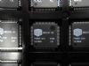
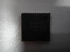
The STV6414ADBCH is a highly integrated I2C bus controlled audio and video switch matrix, optimized for use in digital set-top box applications. It provides the audio and video routings required in a two SCART set-top box design. In an LQFP64 (10 × 10 × 1.4 mm) package, the STV6414ADBCH is compatible with the STV6413.
Parametrics
STV6414ADBCH absolute maximum ratings: (1)VCC12, Supply voltage for slow blanking sections: 13.2 V; (2)VCCAO, Supply voltage for audio drivers: 13.2 V; (3)VCCA, Supply voltage for digital audio sections: 10 V; (4)VDD, Supply voltage for digital sections: 6 V; (5)VCC, VCCBI, Supply voltage for video sections: 6 V; (6)VIN, Input voltage at pin(in reference to GND); (7)Audio pins: 0 to VCCA V; (8)Video pins: 0 to VCC or VCCBI V; (9)Bus pins: 0 to 5.5V; (10)Slow Blanking pins: 0 to VCC12 V; (11)VESD, Maximum ESD Voltage allowed. (human body model: 100 pF capacitor discharged through 1.5 kOhm serial resistor): ±4 kV.
Features
STV6414ADBCH features: (1)I2C bus control; (2)Standby mode with interrupt signal output; (3)Video section, 3 CVBS inputs, 2 CVBS outputs; 3 Y/C inputs, 2 Y/C outputs; Switchable LPFs (low pass filters) on 6; (4)inputs; 6 dB gain on all CVBS/Y and C outputs; Integrated 150 Ω buffers; 2 RGB/FB inputs, 1 tri-state RGB/FB output; (5)with 6 dB adjustable gain (from +3 dB to +9 dB); Video muting on all outputs; 2 slow blanking inputs/outputs; Sync bottom clamp on all CVBS/Y and; (6)RGB inputs, average clamp on C inputs, SVHS switch on C VCR output; Bandwidth: 15 MHz; Crosstalk: 50 dB minimum.
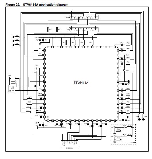
Diagrams